How Does An IR Sensor Work!
Arduino UNO is a microcontroller board- it is the brain of any electronics project. IR sensor, on the other hand, is an infrared rays transmitter and receiver. In the following project, we will learn the working principle of IR sensor followed by its application as a discriminator between black and white surfaces and as an obstacle detector with Arduino UNO.
IR Sensor
FC-51 IR Sensor emits and detected infrared radiations. IR radiations are
part of the electromagnetic spectrum, with wavelength higher than that of
visible light, and are generally invisible to the human eye.
The IR sensor consists of:
1.
IR Emitter LED: Emits
infrared light
2.
IR Receiver: A
photodiode with resistance depending on the amount of IR light falling on it
3.
Distance Adjuster: Changes
detection distance
4.
Vcc Pin: Provides
3–5 V input voltage
5.
Gnd Pin: Ground
input
6.
Out Pin: Transmits
output signal from the sensor to Arduino
7.
Obstacle LED: Turns on
when light falls on IR Receiver
8. Power LED: Turns on when the sensor is connected to a voltage source

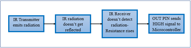
Working of IR Sensor:


Similarly, when the light sent isn't reflected either because there is no surface ahead or the surface ahead absorbs light, the resistance of the receiver rises and a HIGH/1 signal is sent by OUT pin to the microcontroller.
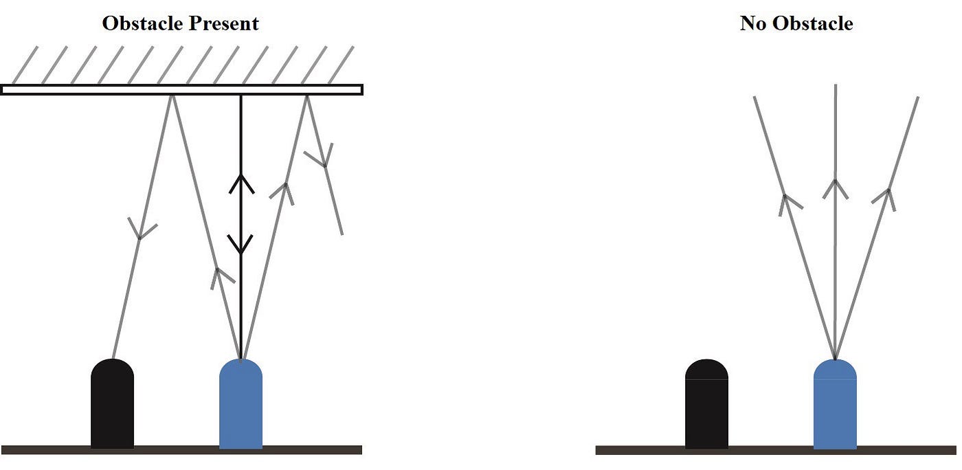
IR Sensor differentiating between black (rough) and white (smooth and reflective) surface

IR Sensor detecting an obstacle
Using IR Sensor with Arduino
Hardware requirements:
1.
Arduino UNO
2.
Arduino Cable
3.
LED
4.
IR Sensor
5.
Jumper Wires
6.
BreadBoard
Software Requirements:
1.
Arduino IDE
2. Copy-paste the code from here:
Connections:

Connect Arduino to Laptop using a USB cable, and upload the code. Open
serial monitor to view results.
EndNote
In the above mini-project, it was shown how the IR sensor can be used
along Arduino to detect obstacles or differentiate between reflecting and
non-reflecting surfaces. IR sensor, along with Arduino is used in many
sensor-based electronic projects like line following car, obstacle avoiding the car, and gesture control robot. To learn more about the project, watch the
video till the end.


I like this article. I was searching on the search engine and found your blog. I get more knowledge and I read a lot of interesting content here. keep doing it. red light therapy for muscle recovery
ReplyDeleteTail lights provide a safety aspect of the vehicle. They show the rear edge of the vehicle to allow other drivers to appropriately gauge the size and shape of the car. In addition, they allow other vehicles to see the car in inclement weather such as rain or snow. If a tail light has gone out, replace it right away.www.protuninglab.com
ReplyDelete